Installing Your Crystal Chip in your slim PSTwo
From Ccwiki
Its very important that you first read through this entire tutorial before you attempt anything!
Here we will cover some common practices and techniques used by pro's to install modchips. In this tutorial we will be installing a Crystal Chip 2.0 in a V15b NTSC U/C slim PSTwo. Let me first point out that some of the points I will be using differ from the official diagram. When I have used alternate points this will be noted. You can use either the official points from the Crystal Chip site or the ones in this tutorial. Also let me point out that the methods discussed in this tutorial are by no means the only methods of installing a Crystal Chip in your console. These are the techniques that I have used to do numerous successful installs. This tutorial will reveal secrets of how the pro's get those installs to look and perform so well. By no means does your install need to look perfect to work perfect, but if you would like it to be both you will find the information on how to do so here. A certain level of soldering experience is also assumed with this tutorial. This means that if you have never picked up a soldering iron before now or have limited solder experience with very small work you should consider practicing on something other then your beloved console or look for professional help with your install. Let it also be know that this tutorial is just that, a tutorial. You and you alone are responsible for your work and your console. Now on with the tutorial.
Contents |
Beginning Your Install
You will of course need to start by Disassembling Your Slim V12-V15 PSTwo . Now lets list the tools and supplies you will need to get this job done. There are multiple suppliers linked to here. I have attempted to link to ones that have the cheapest yet most appropriate and reliable solutions to get this job done.
Necessary Items
- Toothpick or other pointed implement
- Wax Paper
- Tape either electrical or clear packing tap
Recommended Items
- Q-tips and Rubbing Alcohol for clean up.
Here is a picture of some of the tools I use.

Mounting Your Chip
We will first start by locating a good place to mount the modchip to the motherboard. I like to place the modchip in such a location that it wont be burying your solder points or your wires. A good place for this it right above the controller ports.

Its a good idea to insulate that back of the modchip from the motherboard with a thin layer of tape. Electrical tape will do but I like to use clear packing tape as it doesn't get nasty like electrical tape does when it gets warm. I then trim the excess tape from the chip with scissors.

I then place a small blob of hot glue on the PSTwo's motherboard where I plan on mounting the chip. While the glue is still hot press it onto the hot glue blob. I also try and align one of the ground pads on the Crystal Chip with a ground on the PSTwo's motherboard. I do this so I can make a solder bridge directly from the mother board to the modchip. This creates a good ground and well as secures the chip to the motherboard in addition to the hot glue.


Now we can tin all the solder pads on the modchip and build the solder bridge for the ground point of the mochip. Note: This ground point is an alternative from the official diagram. but is electronically equivalent. This technique takes some practice and is not needed, if you find it too difficult to preform you can just use some of your 24GA Stranded Wire.


Preparing Your Motherboard
BIOS Points
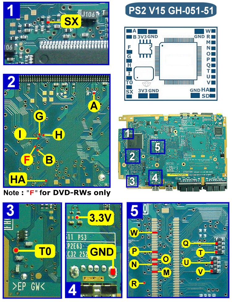
After the modchip has been mounted successfully we will now move on to tinning the BIOS pads on the PSTwo's motherboard. The BIOS points are M, N, O, P, Q, R, T, U, V and W. First locate where these point are on your motherboard in relation to the official diagram. Note: I will be using alternative points here for Q, T, U and V. They are the electronic equivalent of the points specified on the official diagram. Now that you have located these points take your toothpick (or other pointed implement) and dab it into your flux paste. One by one coat each BIOS pad with a small amount of flux. Now with your soldering iron fired up touch your solder to the tip of your iron so that a small amount of solder remains on the tip. Being careful not to bridge other pads, place the tip of your iron to each fluxed pad. The solder should take to the pad and remain, thus tinning the pad. You should only need to place the iron on each pad for about one or two seconds. Lingering longer then this could damage the pad.


Via Points
Now we can move onto tinning the CDVD via's. The CDVD points are A, B, F, G, H, I and HA. Locate the via's on your motherboard with reference to the official diagram. Often times the via's are coated with a type of lacquer that makes it difficult to solder. However this lacquer can be removed with the use of a Fiberglass Pencil or a Hobby Knife. I personally like to use the Fiberglass Pencil as it does a very proficient job of removing the lacquer without damaging the via's or the traces. With the Fiberglass Pencil you simply rub the tip back and forth on the via's like a pencil eraser until you can see solderable copper. The Hobby Knife can be used also but much more care needs to be taken when doing so. Basically with the Hobby Knife method you will be scrapping the via with the sharp tip of the knife until you see bright shinny solderable copper. Here is a before and after using the Fiberglass Pencil.


If you are lucky enough to have a slim that doesn't have the lacquer on the via's you can skip the above part and move onto fluxing and tinning the via's. This process is very similar to how we tinned the BIOS pads before. Take your toothpick or other pointed implement and dab it into your flux paste. Now dab the flux on to each via one by one. Now with your iron ablaze touch your solder to the iron leaving the tip of your iron with a small amount of solder on it. Touch the tip of the iron to the fluxed via's one by one until they are all tinned. If done correctly the solder will take to the via and actually fill the small hole in the via. As before you don't want to linger to long on the via's as damage to them may occur if you do so. Note: I will not be soldering the F via as its only needed for the booting of RW media which many including I do not believe is good for the laser as RW media is much harder for the laser to read.


Wire Preparation
We can now start preparing the 30AWG Kynar wires to be soldered. Start by cutting the wire longer then you think you will be needing with the diagonals (wire cutters), having the wire too long is much better then too short. We need to remove the Kynar from the wire and tin the wire. The best way to do this is with the soldering iron. Ball up a small amount of solder on the tip of your iron. With your iron in one hand and your wire in the other aim them at each other like you would if you were pointing the tip of each of your index fingers together. Lap the wire up onto the tip of the iron where you have your solder ball and roll the iron around the wire in the solder ball. If the iron is hot enough it will melt the Kynar right off and tin the wire all at once. Note: Here a 30 Watt Soldering Iron might do a better job, but more care will need to be taken if you plan on using this iron to solder to the motherboard as well.

Soldering To The Motherboard
Once your wires have all been prepared you can now begin to solder them to the pads and the via's you tinned. Start with the BIOS pads and work so that you don't bury yourself with wires. I like to work from the top down on the pads. Dab your tinned wire into your flux paste so that a small amount remains on the tin. Place this tinned/fluxed wire over the first tinned pad and touch the iron to the tin on the wire. If all goes well the solder will heat and bond to the tin on the pad and the tin on your wire. Once again you don't need to linger longer then a few seconds. Once the solder has taken, give the wire a very light tug to verify that it has bonded well. Work your way down until you have all the BIOS wires soldered. Sticky tack can be used to hold already soldered wires out of your way while you work on new solder joints, tape can also be used.


Once all the BIOS wires have been soldered move onto the CDVD wires following the same procedure.


Now you can solder your TO and SX wires. The TO is a large pad so not much discussion is needed here. The SX point however can be a little tricky for some. The SX point specified in the official diagram is on the side of a very small capacitor. Many rookies damage this capacitor or simply cant solder to the point at all. Much care is needed when soldering to this point. Note: Here I will also be using an alternative solder point for the SX wire. The chip leg shown in the picture below is the electronic equivalent of the SX point in the official diagram. This chip leg can also be tricky. If care isn't taken you can bridge the chip leg next to it.

Wire Routing
Now that we have all the wires soldered to the motherboard (minus the 3v3 wire) we can now start routing the wires back to the modchip and tacking them in place. Here is were you will need to make a decision if you want to use Super Glue or Hot Glue to tack your wires. Hot Glue works very well and is easy to remove if you get into any trouble, but it doesn't give your install that nice clean look that Super Glue can. With Super Glue however you need to be very careful about were and how much glue you use. You don't want to get the Super Glue on anything other then the wires. Keeping it off the motherboard can be done with wax paper under the wire. The wax paper will also help you align your wires side by side when you are routing them over small components. The next series of pictures I will be using super glue and my toothpick (I actually use the red pointed implement in the top picture) to apply the Super Glue. I do not pour the glue right out of the dispenser as this makes it too hard to manage and glue can end up getting all over. I simply pool up a small amount of super glue on a separate piece of wax paper and dip the toothpick into the glue. Take your time and think about how you want the wires routed. In the end if you are patient it will look very nice when your all done.


Soldering To The Modchip
When you have your wires tacked in place how you would like them you can now begin to solder them to the modchip. Keep in mind here that you want to also work so you don't bury yourself with previously soldered wires, work one way or the other. To solder the wires to the modchip I bend the wire in the direction of the pad I want to solder to I let it run long over the pad. I then hold the wire in place with my Tweezers and snip the wire to length with my diagonals. Once the wire is sniped I continue to hold the wire in place with my Tweezers. I then place my soldering iron over the top of the wire and the pad on the modchip. Pressing down lightly the iron will melt the Kynar and solder the wire to the pad all at once.


Soldering Your 3V3 Wire
You are almost there! Just one more wire to solder. Now you will need just a short piece of your 24AWG Stranded Hook Up wire. Strip on end of it and tin it with a decent amount of solder. Dab the tinned end in your flux and solder it to the 3V3 point on the motherboard. Note: here once again I use an alternative point for the 3V3 point. Rout your 3V3 wire over to the 3V3 pad on the modchip and once again use your tweezers to hold the wire in place as you snip it to length with your cutters. This time you will need to physically strip the wire. Scissors can be used to score the insulation if you don't have wire strippers. Once you have stripped the other end of the wire tin it then solder it to the 3V3 point on the modchip.


Flashing Your Chip
Your done!!!! Well almost. You now will need to flash the chip. Flip the console over so its facing right side up. Be careful in doing this as the laser is still loose. Use the technique described in the Disassembling Your Slim V12-V15 PSTwo to do this without damaging your lasers ribbon cables. At this point you can also test to see if your install is correct without having to reassemble the whole PSTwo. Take some sticky tack (tap will also work) and depress the two lid switches. One is right on the rest button and the other is at the rear of the console next to the laser. Place your FW/BM upgrade disc on the spindle plug in your power and AV cable and your controller in port 1.


The moment of truth is here! Tap reset ...... oh geezzz can you feel it! If everything went right the console should boot with the typical PS2 intro then the chip should quickly boot the upgrade disc and you should then see the Crystal Chip logo. A menu will appear that will allow you to upgrade the FW and also install Boot Manger to the CC2.0's cflash. If you have a CC1.0, CC1.1 or CC1.2 you can install Boot Manger to your PS2 Memory Card. It will look like this.
CC2.0 Upgrade disc booting video - Windows Media File 1.8MB
Now your done! Congratulations! Sit back, take a break... what! heck no, get gaming!

